
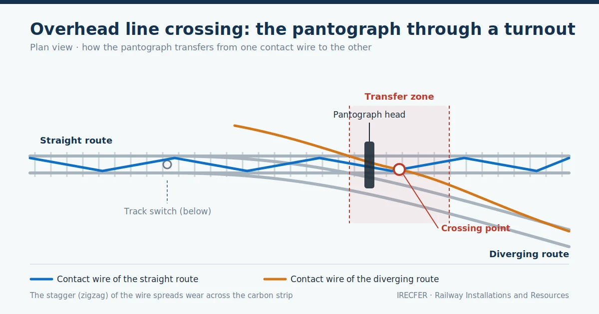
On an electrified line, trains draw current through the pantograph, which runs against the contact wire of the overhead line along the whole route. Where the track is single and straight, that relationship is simple: one wire, one geometry and continuous contact. The problem appears where the track divides. At a turnout, a train can take two different routes, and each route has its own overhead line. Something has to resolve what happens at the point where the two overhead lines meet, and that something is the overhead line crossing.
Overhead line crossings are one of those components that passengers never notice and that, nevertheless, account for a large share of incidents on an electrified line when they are not properly designed, installed or maintained. A pantograph snagging at a crossing can tear down tens of metres of contact wire, take the line out of service for hours and damage rolling stock. In this article we explain what they are, how they work, what types exist, which criteria govern their design and what care they need.
What is an overhead line crossing?
An overhead line crossing is the set of contact line components that resolves the crossing or convergence of two overhead lines above a turnout, a crossover or a junction. In Spanish it is known as an aguja aérea, literally an “aerial switch”, by analogy with the track switch underneath.
It is worth separating the two concepts from the start, because they share a name:
- The track switch is the mechanical device that moves the switch rails and routes the train onto one itinerary or the other.
- The overhead line crossing sits in the catenary, several metres above, and its job is not to route anything, but to guarantee that the pantograph passes from one contact wire to the other without losing current collection and without snagging.
In tramway and trolleybus systems the term carries even more weight, because there the aerial switch does include routing components for the trolley pole. In conventional and high-speed railways, by contrast, we are talking about a purely geometric and mechanical solution: placing the two contact wires in the right position so that the pantograph picks them up and releases them progressively.
Why it exists: the pantograph passing through a turnout
To understand the overhead line crossing, it helps to think about what the pantograph sees. The pantograph head has a limited width, and the contact wire does not run along the exact centre of the track: it describes a controlled zigzag, known as stagger, so that the carbon strip wears evenly instead of grooving at the same point.
When a train enters a turnout, for a few metres it finds itself between two tracks whose centre lines gradually separate. If the overhead line of the diverging route appeared abruptly above the pantograph, there would be a mechanical impact; if the wire of the straight route disappeared abruptly, there would be a loss of contact and arcing. The overhead line crossing prevents both: it organises the entry and exit of each contact wire so that, over a certain length, the pantograph is in contact with both, and the transfer happens smoothly.
That overlap is the heart of the design. It has to be located where the separation between the two track centres allows both wires to sit within the working width of the pantograph head, and it has to be regulated in height so that the incoming wire does not strike the pantograph horn, but is picked up from above and guided along.
Components of an overhead line crossing
An overhead line crossing is not a single part, but an assembly:
- The two contact wires, the one on the straight route and the one on the diverging route, converging in the turnout area.
- The messenger wires of both overhead lines, from which the contact wires are suspended.
- The droppers, which connect the messenger wire to the contact wire and set its height point by point.
- The registration arms or steady arms, which hold the contact wire laterally and determine its stagger. In the crossing area they are especially critical, because the relative position of the two wires depends on them.
- The cantilevers anchored to masts, portals or structures, which support the whole assembly. At overhead line crossings it is common to find double cantilevers or shared masts carrying the overhead line of both tracks at once.
- The crossing fittings, in solutions where the wires physically cross, which hold the relative position and distribute the forces.
- The sectioning components, where the two tracks belong to different feeding sections and have to be separated electrically.
To these are added the tensioning devices, balance weights or automatic tensioning systems that keep mechanical tension constant against thermal expansion, and the electrical connections that guarantee current continuity.
Types of overhead line crossings
Crossed arrangements
In this solution, the two contact wires physically cross, and a fitting at the crossing point keeps them in their relative position and stops one moving with respect to the other. It is the classic solution on conventional lines and in yards, where speeds through the turnout are moderate.
Its advantage is simplicity and robustness. Its drawback is that the crossing point is a singular point: it concentrates mass, alters the dynamic behaviour of the assembly and, at high speed, can cause the pantograph to separate from the wire and produce arcing.
Non-crossing or tangential arrangements
On higher-speed lines, arrangements are used in which the wires never actually cross. Both run close together and broadly parallel over a certain length, one of them slightly higher, so that the pantograph picks up the incoming wire progressively while releasing the outgoing one.
This layout reduces dynamic irregularities, improves the quality of current collection and lessens localised wear. In exchange, it demands far more precise setting out and regulation, and leaves less margin against track settlement or badly adjusted stagger.
Arrangements with sectioning
Where the two converging tracks belong to different feeding sections, or where it is useful to be able to isolate part of the installation in order to work on it, the overhead line crossing incorporates insulating components: section insulators or air-gap section breaks, combined with disconnectors that allow the two sections to be connected or separated electrically.
These arrangements are common on station approaches, in yards, depots and freight terminals, where being able to isolate a group of tracks without interrupting the rest of the service has enormous operational value.
Tramway and trolleybus aerial switches
On tramways, and above all on trolleybus systems, the aerial switch incorporates routing components that guide the trolley pole or the pantograph onto one branch or the other, and in many cases they are motorised and controlled remotely from the vehicle itself or from a control room. These installations are more compact, sit at a lower height and are passed at reduced speeds, but they need frequent maintenance because of the number of movements they withstand.
Design criteria
Designing an overhead line crossing is, above all, a problem of geometry and dynamics. The criteria that weigh most are:
- The position of the transfer point in relation to the track turnout. The aim is to find the zone where the separation between track centres allows both wires to sit within the working width of the pantograph head.
- The stagger of both wires in the crossing area, which has to be calculated jointly rather than track by track, taking into account the lateral displacement of the vehicle and the effect of nearby curves.
- The relative heights of the two contact wires, which determine how the transition happens and whether the pantograph can snag the incoming wire.
- The speed over each route, which governs the choice between a crossed or a tangential solution.
- The type of pantograph and its working width, together with the contact force and the uplift it produces on the wire, especially where several pantographs run raised on the same train.
- Compatibility with the existing infrastructure: gauges, mast positions, structures, tunnels and overbridges, which often dictate the solution more than the calculation itself.
All of this is carried out within the European regulatory framework and the infrastructure manager’s specifications, which set the design parameters for the overhead contact line and for its interaction with the pantograph.
Installation, regulation and commissioning
Installing an overhead line crossing is one of the most delicate jobs on an electrification project, and it is almost always carried out during night-time possessions, with the track closed and coordinated with track works.
The process includes setting out the area, erecting masts and cantilevers, stringing and regulating messenger and contact wires, fine adjustment of heights and stagger, fitting the crossing components or the insulating devices, and making the electrical connections.
Commissioning requires checking the geometry with suitable measuring equipment and, on higher-speed lines, verifying the dynamic behaviour through instrumented test runs that record contact force, wire uplift and the presence of arcing.
One detail that is often overlooked: any subsequent work on the track, such as tamping or renewal, changes the position of the rail and therefore the relationship between track and overhead line. After such work, the overhead line crossing has to be checked and readjusted.
Maintenance and inspection
Maintaining an overhead line crossing combines visual inspection, geometric measurement and analysis of dynamic behaviour:
- Regular visual inspection of the condition of crossing fittings, registration arms, droppers and insulators, looking for abnormal wear, deformation, arc marks or loose parts.
- Measurement of height and stagger, both with manual equipment and with recording vehicles that register the geometry at line speed.
- Monitoring of contact wire wear, which in crossing areas tends to be heavier and less uniform than on plain line.
- Thermography and arc detection, which make it possible to locate poor contact before it causes a failure.
- Review after incidents and after track works, as noted above.
- Particular attention in adverse weather: ice on the contact wire, strong winds and sharp temperature swings all alter the geometry and the quality of current collection.
Typical problems and how to avoid them
The most frequent incidents at overhead line crossings have recognisable causes:
- The pantograph snagging the incoming wire, almost always because of a badly regulated relative height or stagger outside tolerance.
- Localised contact wire wear, caused by repeated loss of contact at the crossing point.
- Loss of contact and arcing during the transfer, which degrades both the wire and the carbon strip and shortens the life of both.
- Misadjustment after track works, where the track is worked on without checking the overhead line afterwards.
- Lack of traceability, where measurements and adjustments are not recorded and it becomes impossible to know how the installation has evolved.
Most of these are prevented in the same way: a design that takes the real condition of the track into account, precise regulation during installation, and a maintenance plan that includes periodic measurement and a systematic review after any work on the infrastructure.
Innovation: towards a monitored overhead line crossing
The trend in the sector is to reduce purely visual inspection and replace it with data. Recording vehicles register geometry and contact force continuously, onboard systems fitted to commercial trains allow the line to be monitored without dedicated runs, and dynamic simulation models of pantograph–overhead line interaction make it possible to anticipate how a crossing will behave before it is built.
Alongside this come improvements in materials and in the design of crossing fittings, aimed at reducing the mass concentrated at the singular point, and the use of sensors that detect impacts or abnormal forces and give warning before a failure occurs.
Conclusion
The overhead line crossing is the point at which the catenary resolves what the track has already resolved below: the existence of two possible routes. Its job is to let the pantograph move from one overhead line to the other without losing current and without taking an impact, and achieving that means looking after geometry, regulation and maintenance with a level of precision that leaves no room for improvisation.
It is also a component that concentrates risk: incidents at overhead line crossings are expensive, they affect the service and they can damage rolling stock. That is why they deserve to be treated as what they are, a singular point of the installation, and given the design, installation and monitoring they require.
Do you need overhead line crossings installed or inspected on your network?
At IRECFER we design, install and maintain railway electrification systems in Spain, Portugal, the Nordic countries and Latin America, including singular overhead line areas such as crossings, section breaks and station and terminal approaches. We have specialist teams, experience of night-time work under possession, and the capacity to take on anything from one-off interventions to the full electrification of a line.
Contact us to discuss your project or request a quote with no obligation.

