
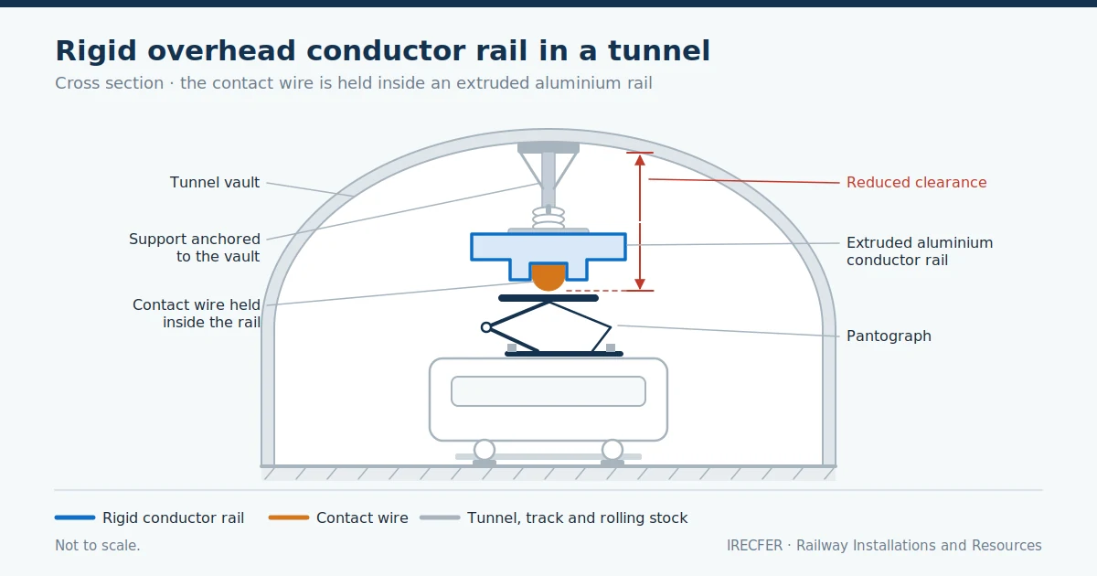
In a metro tunnel where the crown sits just a few centimetres above the train roof, conventional electrification simply does not fit: there is no height for a messenger wire, droppers and a contact wire with its sag, and no room for the tensioning equipment at the ends of each tension length. That clearance problem, present in almost every underground works and in many refurbishments of old tunnels, is what the rigid overhead conductor rail solves.
The rigid overhead conductor rail replaces the set of suspended cables with an extruded aluminium profile that holds the contact wire along its entire length. The conductor rail acts as mechanical support and conductor at the same time, is fixed directly to the structure by means of short supports, and needs no tensioning. In exchange for a minimal construction height, it imposes other demands: mounting accuracy, management of thermal expansion and careful design of the transitions.
This article explains what the rigid overhead conductor rail is, what it consists of, where it is installed, what advantages and limitations it has, how it is erected and maintained, and on what criteria to decide whether it is the right solution for a given project.
What the rigid conductor rail is and how it differs from flexible overhead line
The rigid overhead conductor rail is an overhead electrification system in which the contact wire — the copper conductor that the pantograph, the current collector mounted on the train roof, rubs against — is embedded in a large-section aluminium extrusion that runs continuously above the track. The conductor rail rests on supports fixed to the tunnel crown or to a structure, with a spacing between supports far shorter than the distance between masts on a conventional line.
In a flexible overhead line the contact wire hangs from a messenger wire by means of droppers — the vertical ties that link both conductors — and the whole assembly is kept under tension by automatic tensioning equipment. That mechanical tension sets the geometry of the wire and allows long spans, elasticity and high speeds. In the rigid conductor rail there is no messenger wire, no droppers and no tensioning: the geometry is set by the conductor rail itself and by the position of its supports.
The most important technical consequence is dynamic behaviour. A flexible overhead line has an elasticity that varies along the span — greater at mid-span, lower next to the supports — and the design aims to make that variation as uniform as possible. The rigid conductor rail, by contrast, is practically undeformable under the uplift of the pantograph: the quality of current collection does not depend on the elasticity of the system, but on the geometric accuracy with which it has been erected. Any step, misalignment or protrusion at a joint translates directly into a variation in contact force, a relationship developed in the article on pantograph overhead line interaction.
The second difference is electrical. The aluminium conductor rail provides a conducting cross-section far greater than that of a conventional contact wire, even adding the messenger wire and the feeders — the supply cables running in parallel to reinforce the overhead line. That translates into a lower voltage drop and a high current-carrying capacity, useful above all in direct-current systems with frequent train starts.
Components: conductor profile, contact wire, supports and joints
Although the system looks simple compared with a flexible overhead line, each element performs a specific function and leaves little room for improvisation on site.
- Conductor profile. An extruded aluminium bar, open along its lower face, manufactured in sections that are assembled into a continuous conductor. Its geometry pursues three objectives: enough stiffness not to deflect between supports, a high conducting cross-section, and a lower groove able to retain the contact wire through the elastic pressure of its lips.
- Contact wire. The same copper or copper-alloy conductor used in flexible overhead line, housed in the groove of the conductor rail so that only its lower face is exposed, the one that rubs against the pantograph collector strip. Being embedded, it carries no tensile load and can be replaced when worn without dismantling the conductor rail.
- Each support combines a bracket fixed to the structure — chemical or mechanical anchors in the crown, or short cantilevers where the fixing is lateral — an insulator and a clamping piece. The support allows height and lateral position to be adjusted: much of the commissioning work takes place there.
- Splice joints. Sections are spliced with bolted splice plates that must guarantee mechanical continuity, alignment without a step, and electrical continuity. They are the critical point of the system: a poorly tightened joint is both a dynamic defect and a hot spot.
- Expansion joints and overlaps. Since aluminium expands and the conductor rail is not tensioned, the installation is divided into sections with devices that absorb longitudinal movement while maintaining electrical continuity.
- End approach and transition pieces. At the ends of each section, and at the links with flexible overhead line, ramps are fitted to guide the pantograph and prevent impacts against the end of the conductor rail.
To this are added the usual electrical elements: feeder connections, section insulators, bonding jumpers, earthing and protection. Turnout areas, where two conductor rails must cross or overlap so that the pantograph can pass from one track to another, are a particular case related to the design of overhead line crossings in conventional overhead line.
Where it is installed: tunnels, metros, underground stations and restricted clearances
The criterion for its use is almost always the same: lack of height. The rigid conductor rail needs a very small construction height — the distance between the contact plane and the highest part of the assembly — because conductor and support are practically the same element. Where a flexible overhead line requires a larger excavated section or a lowered trackbed, the rigid conductor rail fits.
Hence its characteristic fields of application: running tunnels, metro and urban rail networks, underground and through stations, cut-and-cover tunnels and urban decking, passages beneath existing structures, and depots and workshops, where it is also useful to isolate specific sections safely. It is likewise frequent in refurbishments: electrifying an old tunnel or renewing an existing installation without enlarging the section is a scenario where the rigid conductor rail is often the only alternative without heavy civil works.
On mixed lines, the rigid conductor rail coexists with flexible overhead line: the conductor rail in the underground section and conventional overhead line in the open air. The delicate point is the transition, which must ensure that the pantograph passes from one system to the other without loss of contact or impact. That link, with its overlaps, ramps and height adjustments, is the subject of the article on hybrid overhead line.
Advantages: clearance, electrical safety and reliability
- Reduced clearance requirement. This is the whole point of the system: it makes it possible to electrify tunnels of tight section, reduce the volume of excavation in new build, and keep the passage clearance beneath existing structures.
- No tensioning equipment. There are no counterweights, pulleys or tension-length anchors, so a set of components that in flexible overhead line require periodic inspection and take up room at the ends of each tension length disappears.
- Safety against wire failure. The wire is housed in the conductor rail and carries no tensile load: should it develop a defect, there is no stored elastic energy to bring the conductor down onto the track, a scenario that in flexible overhead line forces lengthy closures.
- High current capacity. The aluminium cross-section reduces voltage drop and the need for reinforcing conductors, which simplifies the supply arrangement on intensively operated systems.
- Robustness against snagging. With no droppers or suspended cables, the risk of a defective pantograph catching and tearing down parts of the system is considerably reduced.
- Predictable maintenance. Wear is concentrated on the contact wire, which is replaceable, and inspections focus on a few critical points: joints, anchors, insulators and expansion devices. The conductor rail, the most expensive element, barely degrades because it is subject neither to permanent tension nor to friction.
Limitations: speed, thermal expansion and cost per kilometre
The first limitation is speed. The absence of elasticity means the system tolerates geometric irregularities poorly: the higher the speed, the smaller the margin for height deviations, steps at joints or changes in the gradient of the wire. The rigid conductor rail has traditionally been used on moderate-speed systems and today covers wider ranges, but the maximum permissible speed depends on the specific system, on its installed geometry and on what the infrastructure manager accepts; it is not a generic figure that can be taken for granted.
The second is thermal expansion. A continuous, untensioned aluminium conductor changes length with temperature, and that movement is managed by dividing the installation into sections with free ends and expansion devices. Each of those points is a discontinuity that the pantograph has to cross, so their number and location form part of the design from the outset, conditioned by the actual temperature range of the site.
The third is cost per kilometre. The conductor rail contributes a great deal of conducting material and calls for a high density of supports, with their anchors and insulators, which puts the initial investment above that of an equivalent flexible overhead line. That difference is only offset when the system avoids civil works or when maintenance and unavailability over the service life outweigh the investment. To this are added two operational demands: erection more precise than that of a conventional overhead line, and the need for an access platform beneath the crown for any intervention, usually within short night-time possessions.
Erection: setting out, alignment and commissioning
Erecting a rigid conductor rail is, above all, a matter of surveying and fine adjustment. The usual sequence runs through the following stages.
- Setting out. The position of each support is defined from the track centre line and the actual rail level, not from theoretical drawings. If the track is not yet in its final position, the work is based on setting-out references related to it, because wire height and stagger are always measured with respect to the finished track. A centre line corrected afterwards means redoing the adjustment support by support.
- The crown or the structure is drilled and the anchors are placed, with whatever pull-out testing the supervising engineer requires. The fixing must take into account the actual condition of the concrete or lining and avoid interference with reinforcement and existing installations.
- Supports and insulators. Brackets, insulators and clamping pieces are erected, leaving the adjustment open for later fine tuning.
- Conductor rail installation. Sections are lifted and spliced with their joint pieces, tightened to the specified torque and checked so that no step remains on the running face, and the gaps provided for the expansion joints are respected.
- Contact wire insertion. The wire is fed into the groove of the conductor rail by a machine that guides and embeds it continuously, checking that it is fully seated along its whole length.
- Geometric commissioning. Height, stagger and gradient of the wire are adjusted support by support, using a total station or dedicated measuring equipment. This is the stage that determines the final quality of the system.
- Electrical work and testing. Continuity, feeder connections, section insulators, earthing, insulation measurements and thermographic checks of the joints. The usual closing step is a verification run with a vehicle fitted with a measuring pantograph, which checks geometry and contact force at the intended speed.
Beneath a tunnel crown, overhead line, signalling, communications, ventilation and lighting all coexist, and interference between installations almost always appears during the anchoring stage. Planning the order of the works within each available possession avoids having to redo fixings already installed.
Maintenance: inspections, wear and joint adjustment
Maintaining a rigid system is simpler than maintaining a flexible overhead line, but it is not non-existent, and it concentrates on very specific points.
Visual inspections run along the conductor rail looking for contact wire displaced within its groove, dirty or cracked insulators, loose bolts and signs of abnormal rubbing. In underground environments, brake dust deposited on the insulators is a degradation factor that calls for periodic cleaning. Geometric measurements verify the height and stagger of the wire and detect deviations from the original installation, either with a recording vehicle or with portable equipment.
Monitoring wear of the wire is done by measuring the remaining thickness or surface on the rubbing face; once the limit defined for that installation is reached, the wire is replaced section by section, taking advantage of the fact that the conductor rail stays in place.
Joint adjustment deserves specific attention. Splices between sections must retain their tightening torque and alignment, and expansion joints their freedom of movement: a device blocked by dirt or corrosion transmits loads to the conductor rail and its anchors. Thermography is the most effective tool for detecting degraded joints before they fail, because a joint with poor electrical contact heats up under load. Intervals and intervention thresholds are set out in the overhead line maintenance plan for each installation, which depends on the infrastructure manager and on operating conditions.
When to choose it for a project
The decision is not made out of preference for one system, but by comparing specific constraints.
- Available clearance. If the free height does not allow a properly designed flexible overhead line, the discussion ends there: the rigid conductor rail is the solution.
- New build or refurbishment. In new build, the saving in tunnel section can comfortably offset the extra cost of the system; in refurbishment, avoiding clearance enlargement is usually decisive.
- Operating speed. The higher the target speed, the more weight the geometric requirements carry and the more justified it is to study alternatives or mixed solutions.
- Current system and traffic density. Direct-current operations with frequent trains benefit from the conducting cross-section of the conductor rail and from the simplification of the supply arrangement.
- Maintenance windows. Where possessions are short and scarce, a system with fewer moving parts and no tensioning equipment reduces recurring work beneath the crown.
- Safety and availability. In long tunnels, the cost of an incident involving a conductor coming down is very high, and the retention of the wire inside the conductor rail weighs on the decision.
- Continuity of the alignment. If the rigid section is sandwiched between open-air sections, the number of transitions and their effect on current collection must be assessed, along with the cost of the cantilevers and other elements of the adjacent conventional overhead line.
The useful analysis is one of life-cycle cost: investment, civil works avoided, expected maintenance and unavailability. In underground installations that sum usually tips towards the rigid system; on open-air, high-speed alignments it rarely does.
Conclusion
The rigid overhead conductor rail is not a simplified version of the flexible overhead line, but a system with its own logic: it replaces mechanical tension with geometric precision and reduces construction height to a minimum. That choice solves the clearance problem in tunnels and urban networks and provides a substantial conducting cross-section, in exchange for a more demanding erection process, specific management of thermal expansion and a higher initial investment. Its performance depends, more than in any other electrification system, on the quality of the setting out and the commissioning. And on projects with both underground and open-air sections, the point to study before any other is the transition between the two systems.
Do you have an electrification project with sections in tunnel?
IRECFER delivers railway electrification projects that include rigid conductor rail, flexible overhead line and the transitions between them, as well as traction substations, signalling and communications, power lines and railway civil works, with its own teams in Spain, Portugal, the Nordic countries and Latin America. We can support you from the study of alternatives and detailed design through to erection, commissioning and verification testing. If you wish to assess which system best suits your alignment and your working windows, contact us and we will look at your case.

