
An electrified line almost never fails because of the wire itself, but because of the geometry with which that wire has been hung. Poorly distributed stagger, unbalanced droppers or a jammed balance weight all end up producing the same symptom: loss of contact, arcing, uneven wire wear and, in the worst case, a dewirement that closes the line for hours.
The flexible overhead line is the most widespread overhead electrification system on both conventional and high-speed railways. Its name comes from the shape the messenger wire takes when hung between two supports, and its principle is simple: a contact wire suspended from a second wire by droppers, mechanically tensioned and held laterally so that the pantograph sweeps it evenly. What is not simple is building it to the precision that current collection at speed demands.
This article covers the complete system: its components, the geometry that has to be respected, how thermal expansion is dealt with, the differences between conventional and high-speed lines, installation on site and the weak points worth watching in service.
What a flexible overhead line is and why it is the most widespread system
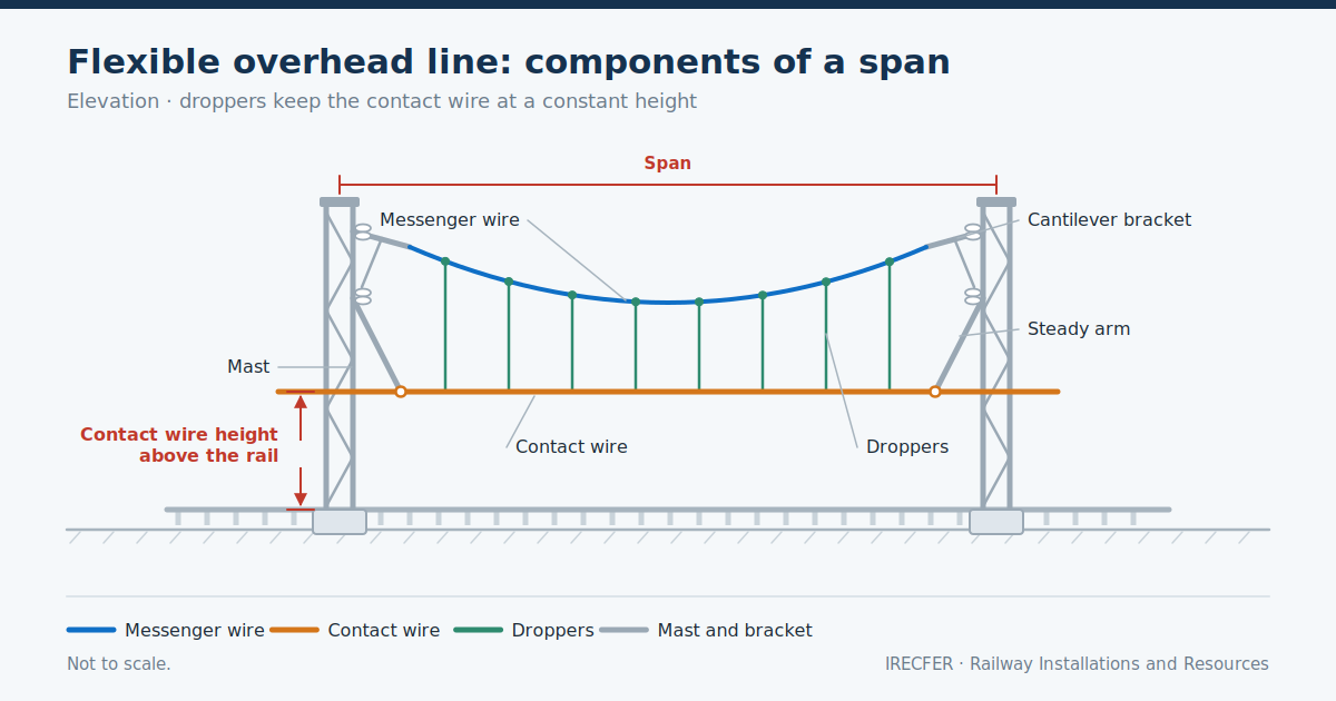
A flexible overhead line is a contact line made up of at least two longitudinal conductors: an upper wire, the messenger wire, which carries the weight of the assembly, and a lower conductor, the contact wire, which is the one that actually rubs against the train’s pantograph. Between them sit the droppers, short vertical elements that suspend the contact wire from the messenger wire at regular intervals. The result is a contact conductor that is virtually horizontal across the whole span, even though the wire holding it up does describe a curve.
That is precisely the reason for its dominance. A single wire strung between two masts sags under its own weight and forces the pantograph to rise and fall continuously. By introducing the messenger wire and grading the length of each dropper, the contact wire is kept at a practically constant height and the pantograph runs with a far more stable contact force. On top of that, the system is light, accepts long spans and adapts well to alignments with curves, changes of gradient and tunnels of sufficient clearance.
The second reason is cost and maintenance: it uses standardised components, it is strung with familiar plant and it allows damaged elements to be replaced without dismantling whole sections. Against it, the rigid overhead conductor rail is a better answer where clearance is tight, such as tunnels with a restricted section, but it is more expensive per kilometre. On many lines both systems coexist and are joined by a hybrid overhead line in the transition zones.
Components: messenger wire, contact wire, droppers and feeders
The messenger wire is the upper supporting cable. It works in tension and absorbs the self-weight of the assembly plus ice and wind loading. It is usually a stranded copper or copper alloy cable, chosen for its balance between mechanical strength and conductivity, because in addition to its structural role it takes part in carrying current. Its cross-section and composition are set in the electrification design according to the supply voltage, the power demand and the climatic conditions of the area.
The contact wire is the lower conductor, the one that delivers current to the train. It is a copper or copper alloy profile with two lateral grooves that allow it to be gripped by clips without intruding on the underside, which must be kept clear for the pantograph’s carbon strip. It is the most critical element of the system: it wears with use, loses section and, when that loss exceeds the admissible limit, it has to be replaced. Its behaviour under the passing pantograph is covered in detail in the article on pantograph overhead line interaction.
The droppers are the vertical elements joining messenger wire and contact wire. They may be of flexible cable or rigid, and their length differs at every point of the span, because they have to compensate for the sag of the messenger wire. On high-performance overhead lines, conductive droppers are used: as well as supporting, they carry current between the two wires and reduce the voltage drop.
The feeders are the conductors that bring energy from the traction substation to the contact line, or that electrically reinforce the overhead line in parallel along the alignment. They do not rub against the pantograph: they run along the upper part of the masts and are connected to the overhead line at defined points. The assembly is completed by equipotential connectors, rail return connections and the earthing arrangements for the whole metal structure.
Cantilevers, steady arms and supports
The supports are the structures that hold up the overhead line: individual masts on one side of the track, rigid or flexible portals spanning several tracks, or anchorages to the crown and side walls in tunnels. Their foundations and sizing depend on the tensile forces in the wires, the wind conditions of the area and whether the support is on straight track, on a curve or at a singular point such as an anchorage or a section break.
The cantilevers are the arms that reach out from the support towards the track and hold the messenger wire and the contact wire in position. They are normally made up of a diagonal tube working in compression, a stay working in tension and the insulators that electrically separate the live part from the earthed structure. They are adjusted on site to leave each conductor at its exact height and lateral position.
The steady arm is the horizontal element, usually an aluminium alloy tube, that holds the contact wire laterally and imposes the stagger specified at each support. It is a small but decisive part: if it is slack, the wire moves; if it is stiff or badly oriented, it introduces a hard spot that the pantograph feels as a blow. On curves, the steady arm works in tension or in compression depending on the position of the support relative to the inside or outside of the curve, and the installation must respect that criterion.
At turnouts we find overhead line crossings, the points where two contact wires from different tracks cross over or transfer. These are areas of complex geometry, with specific crossing fittings and an adjustment that has to guarantee that the pantograph passes from one wire to the other without snagging or abrupt steps in height.
Geometry: height, stagger and span
The geometry of the overhead line is defined by three main parameters. The contact wire height above the running surface determines the working position of the pantograph. There is a nominal design height and an admissible range between a maximum and a minimum, and these are not universal: they depend on the electrification system, on the clearance available and, above all, on the infrastructure manager’s specification and the European regulatory framework applicable to the line. In tunnels, underbridges and beneath overbridges the height drops, and that transition has to be made with gentle gradients so that the pantograph follows it without losing contact.
Stagger is the horizontal offset between the contact wire and the track centre line at each support. It is applied alternately, to one side and then the other, so that the wire traces a zigzag along the alignment. The aim is for the pantograph’s carbon strip to wear evenly across its whole width rather than at a single point. On curves, stagger does not follow the same criterion as on straight track: the sag the wire describes between supports and the position of the vehicle’s pantograph within the curve both have to be taken into account.
The span is the distance between two consecutive supports. A long span makes the installation cheaper, because it reduces the number of masts and foundations, but it increases the sag of the wire between supports and the wind-induced displacement, so there is a trade-off. Maximum span values are set in the design according to speed, wind exposure and curve radius, and they are systematically shortened on tight curves and in exposed locations.
The three parameters are related: reducing the span allows a smaller stagger, and increasing the height forces a review of the clearance of supports and cantilevers. That is why geometry is always set out as a whole.
Tensioning: balance weights and automatic tensioning against thermal expansion
Copper expands with heat and contracts with cold. Over a tension length of several hundred metres that change in length is perfectly noticeable, and if the wires were rigidly anchored at both ends the mechanical tension would vary with temperature: in summer the wire would sag and in winter it would work well above its design value, with a risk of breakage.
The usual solution is automatic tensioning by balance weights. At the ends of the tension length, each conductor is anchored to a set of pulleys from which a stack of weights hangs. The arrangement keeps the tensile force in the wire constant regardless of temperature: when the conductor expands, the weights drop and take up the excess length; when it contracts, they rise. The pulleys usually have a reduction ratio so that the weight required is manageable and the travel of the stack is proportional to the expected elongation.
Two installation concepts follow from this. The tension length is the stretch of overhead line between two tensioned anchorages; its maximum length is limited by the admissible travel of the balance weight and by the friction accumulated in the cantilever pulleys. The midpoint anchor is the central anchorage of the tension length that stops the assembly drifting longitudinally towards one end and shares the expansion to both sides.
Between consecutive tension lengths, mechanical and, where applicable, electrical continuity has to be provided. This is resolved with overlaps in which the two contact wires run in parallel for a few spans and the pantograph transfers from one to the other progressively. Where two supplies also have to be electrically separated, an overhead line section break is used, which may be a simple overlap or incorporate insulation. There are also uncompensated overhead lines, rigidly anchored, reserved for sidings and shunting areas where the variation in sag is not critical.
Types according to line speed
Not all flexible overhead lines are alike. The maximum speed of the line directly conditions the design, because the phenomenon that limits current collection is wave propagation in the contact wire: as the train approaches the speed at which those waves travel along the wire, the pantograph starts to lose contact systematically.
On conventional and moderate-speed lines, a two-conductor overhead line is enough — messenger wire and contact wire — with a simple dropper arrangement and moderate mechanical tensions. This is the most common system on the conventional network, suburban lines and freight branches, and it accepts relatively long spans.
On high-speed lines the mechanical tension of the conductors is raised, the span is shortened, the distribution of droppers is refined and particular care is taken over the uniformity of elasticity along the span. The aim is for the contact wire to respond in the same way at mid-span as next to the support, because any discontinuity translates into an oscillation that the pantograph amplifies at speed.
There are also configurations with a third, intermediate conductor between messenger wire and contact wire, the auxiliary messenger wire, used to even out elastic behaviour in certain designs. The choice is not only a matter of speed: the power to be carried, the frequency of train paths, whether the electrification system is direct or alternating current and the environmental conditions of the corridor all play a part.
Installation on site: stringing, adjustment and tensioning up
Installation follows a fairly stable sequence. First come the foundations and the erection of supports, set out according to the design and checked for position and plumb before going any further. A mast that is out of plumb forces the cantilever adjustment to be strained later on, and that error carries through to the contact wire.
Next, cantilevers and insulators are fitted, pre-assembled in the workshop wherever possible to reduce time working on track. Then comes the stringing of conductors, using an engineering train or a road-rail vehicle equipped with drums and a stringing brake. It is done under controlled mechanical tension, without dragging the conductor over the ballast, because any mark on the underside of the contact wire becomes a point of accelerated wear.
With the wires in place, the work moves on to geometric adjustment: height and stagger are set support by support, droppers are cut and fitted to the length corresponding to each position in the span, and the steady arms are adjusted. This is the phase that most determines the final quality of the system and the one that takes the most time.
Tensioning up consists of releasing the balance weights and letting the assembly take up its working position. From then on the geometry is checked under load, deviations are corrected, and electrical continuity, equipotential connections and earthing are verified. The usual closing step is a recording run and a pass with an instrumented pantograph before commercial traffic is authorised.
Almost all of this is carried out during night-time possessions, with the line closed and to tight deadlines, which means planning materials, plant and personnel in detail and leaving the track each night in a condition to be handed back to traffic.
Maintenance and weak points of the system
The flexible overhead line is a robust system, but it has points where incidents concentrate. The first is contact wire wear, which is not uniform: it accelerates in starting and braking areas, on steep gradients, at overhead line crossings and wherever the geometry presents a hard spot. It is monitored by measuring the remaining section in periodic campaigns.
The second is the droppers, subject to fatigue from the continuous oscillation of the wire. A broken or detached dropper leaves a stretch unsupported and alters the local height of the contact wire, with a risk of the pantograph snagging. The third is the balance weights and their pulleys: a weight stack seized by corrosion or ice, or that has bottomed out, stops compensating for expansion and throws the whole tension length out of adjustment.
To these can be added the insulators, sensitive to salt, industrial or dust contamination, which can lead to flashover; and the electrical connections, where a defective tightening generates heating and progressive degradation. Section breaks and overhead line crossings also account for a good share of the faults, as they are the points of most complex geometry.
The answer is a structured plan of visual inspections, geometric measurements, dynamic recording and thermography, combined with planned replacement of wearing elements, as set out in the article on overhead line maintenance.
Conclusion
The flexible overhead line works well because it turns an electrical problem into a problem of geometry and cable mechanics, and both are under control when the installation is carried out rigorously. Failures rarely come from a mistaken design: they come from a displaced support, a badly measured dropper or a balance weight that has stopped moving. The value of an installation therefore lies as much in the design as in the execution on track and in the maintenance plan that follows it. Any decision on height, span or tensioning must be taken against the infrastructure manager’s specification for the particular line, never by analogy with another project.
Do you have a railway electrification project?
IRECFER carries out railway electrification works in Spain, Portugal, the Nordic countries and Latin America, from the installation of flexible and rigid overhead line to traction substations, signalling and associated civil works. We can take part from the detailed engineering stage through to tensioning up and support in service. If you have a line to electrify, renew or maintain, contact us and we will look at the scope with you.

