
An electric train carries no energy on board: it draws it from the contact wire at every instant and returns it through the rail. This means the line has to deliver power exactly where the train is, at the moment it pulls away or climbs a gradient, and do so at a voltage that stays within an acceptable margin. The element that makes this supply possible is the traction substation, the installation that connects the general electricity network to the overhead line and adapts the energy to the form the rolling stock needs.
For anyone working on site or in maintenance, the substation is the least visible part of the system. The overhead line can be seen, measured and adjusted; the substation is an enclosed compound of switchgear cubicles, transformers and protection panels, and much of what it does happens inside tripping logic and on remote-control screens located hundreds of kilometres away.
This article covers it from end to end: where the energy comes in, what equipment transforms it, how DC and AC installations differ, how it is operated from a control centre, what criteria govern its design, and which errors appear most often during installation and commissioning.
From the general electricity network to the overhead line: the path of the energy
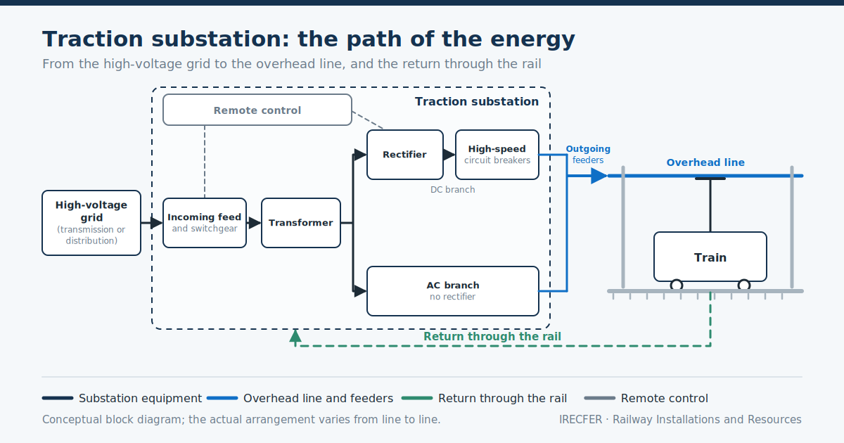
The energy that moves a train comes from the general electricity network, not from generation owned by the railway. The traction substation connects to the high-voltage transmission or distribution network through an incoming supply which, depending on the area and the infrastructure manager, may be overhead or underground and may come from one or several different points on the network. That supply enters the high-voltage compound, where it is metered, protected and switched.
From there the path depends on the system. In direct current, the incoming voltage is stepped down by a transformer and converted to DC by a rectifier group, and the output feeds the overhead line through high-speed circuit breakers. In alternating current, the substation steps the network voltage down to the traction value and delivers it directly to the overhead contact line, with no conversion, but with particular attention to how it connects to the three-phase network.
The circuit closes through the rail. The current the train takes from the contact wire via the pantograph — the articulated roof-mounted mechanism that maintains sliding contact with the overhead line — returns to the substation through the running rails and the associated return conductors. That return path governs the earthing of the installation, step and touch voltages, compatibility with signalling track circuits, and the behaviour of the protection system.
Between the substation and the overhead line there is also a distribution arrangement. The supply cables, known as feeders, link the outgoing cubicles to the connection points on the overhead line. The overhead line is not a single continuous conductor from one end of the route to the other, but a set of independent sections delimited by overhead line section break. Those sections are opened and closed with disconnectors, which allow a specific area to be isolated without de-energising the whole line.
Main equipment: transformers, rectifiers, circuit breakers and protection
Although the configuration varies with the system and with each infrastructure manager’s specifications, the functional blocks recur. It is worth identifying them before moving on to the differences between DC and AC.
- High-voltage compound or cubicles. The point of entry. It contains the switching and breaking equipment on the network side, the voltage and current instrument transformers that feed protection relays and meters, and the surge arresters that limit overvoltages of atmospheric and switching origin. It may be outdoors or housed in metal-clad cubicles under cover.
- Traction transformer. Steps the network voltage down to the value the next stage needs: in DC it feeds the rectifier, in AC it delivers the overhead line voltage directly. Its cooling, insulation and load regime are defined for a duty with very pronounced peaks, not for a flat demand.
- Rectifier group. Only in direct current installations. It converts AC to DC by means of diode bridges, in multi-pulse configurations that reduce the harmonic content injected into the network and the ripple reaching the overhead line.
- Circuit breakers and switchgear. On the overhead line side of a DC substation, high-speed circuit breakers are used, capable of interrupting high short-circuit currents in very short times. In AC, high-voltage switchgear of the type common in electricity networks is used, adapted to traction duty.
- Disconnectors and earthing. They allow circuits to be visibly isolated and connected to earth so that work can be carried out. Their interlocking with the circuit breakers is what guarantees that a disconnector cannot be opened on load, nor an earth applied with the line energised.
- Protection and auxiliary services. Relays, metering equipment, batteries and chargers, control panels, lighting, climate control and fire detection and suppression systems. The auxiliary services are what keep the substation’s logic alive when the main supply fails.
Protection engineering deserves attention in its own right. What is being protected here is a very particular circuit: a long, exposed overhead line with a moving load and with starting currents that can look like a fault. Telling a legitimate consumption peak from a remote short circuit is resolved by combining current criteria, rate-of-rise of current criteria and, depending on the system, distance criteria.
DC and AC substations
The difference between the two families lies not in the building, but in what the installation does with the energy and how that energy is distributed along the line.
Direct current
In 3 kV DC railway electrification and in DC systems generally, the substation transforms and rectifies. The traction voltage is comparatively low, so for a given power the currents are high. Three consequences follow: large cross-sections in overhead line conductors and feeders, significant voltage drops along the section supplied, and substations relatively close to one another.
Breaking in DC is more demanding than in AC, for reasons inherent to the nature of the current that are set out in the article on that system, and that demand shapes all the switchgear on the overhead line side: high-speed circuit breakers and protection based on the rate of rise of current. Corrosion from stray currents, which escape the return circuit towards buried metal structures, is another phenomenon specific to DC that makes rail insulation and drainage measures important.
Alternating current
In 25 kV AC railway electrification there is no rectification: the substation steps the network voltage down and supplies the overhead line single-phase at industrial frequency. Because the voltage is much higher, the currents are lower for the same power, conductors can be lighter and the spacing between substations is greater.
In exchange, issues arise that do not exist in DC. The load is single-phase on a three-phase network, which creates unbalance and makes it necessary to distribute the phases between successive substations and to electrically separate sections fed from different phases, by means of neutral sections that the train coasts through without drawing current. In addition, an AC overhead line behaves as a circuit with appreciable inductance and capacitance, with induction effects on nearby installations that have to be assessed.
Autotransformer arrangements are a frequent variant: they carry the energy at a higher voltage between the substation and the autotransformer points, which reduces the voltage drop and allows substations to be spaced further apart. The choice depends on the expected traffic, the line profile and the connection points available on the network.
Remote control and supervision: how a substation is operated
Traction substations normally operate without permanent staff. They are operated from an energy control centre, which may or may not be integrated with the traffic control centre, and which receives status signals and measurements from all the installations in its area and issues switching commands.
The typical architecture has three levels. At process level are the primary equipment and its actuators. At installation level, the bay control units and protection relays collect signals, execute interlocks and manage local switching. At remote control level, the control centre brings together the indications from several substations and allows circuit breakers and disconnectors to be operated, sections to be isolated for work and the state of the line to be monitored.
Communication between levels relies on standardised protocols from the electricity sector, with a clear trend towards architectures that replace much of the signal wiring with digital communication. This simplifies installation, but shifts complexity to configuration and testing: the error is no longer a badly connected wire, but a configuration file.
Three functions carry particular operational weight. Isolation of a section for work, with its verified sequence of opening, proving dead and applying earths. Restoration after a trip, automatic or manual depending on the fault detected. And event and disturbance recording, which makes it possible to reconstruct an incident to millisecond accuracy.
Design: power, substation spacing and redundancy
Sizing does not start from a catalogue but from an operational study. The planned timetable is taken, with its train types, formations, speeds and frequencies; the real line profile is applied; and the instantaneous consumption at each point of the route is simulated to obtain current peaks, voltage drops and the energy absorbed over the course of the day. The main decisions follow from that study:
- Installed power and overload rating. Traction equipment works with highly variable load cycles, so continuous and temporary overload ratings are defined rather than a single value.
- Number and location of substations. The aim is for the voltage at the pantograph to stay within the permissible margin at the least favourable point and under the most demanding operating assumption. The resulting spacing depends on the system, the traffic and the profile, and is determined project by project; it is not a value that can be carried across from one line to another.
- Network connection points. The substation has to connect where the network can accept the power requested with the quality required. The availability of supply points often determines the site as much as the geometry of the line does, or more.
- Redundancy and degraded operation. What happens if a substation is out of service is analysed. The usual approach is to duplicate equipment within the installation and to provide for the adjacent substations to take on the intermediate section, even if with traffic restrictions.
- Space, access and easements. A substation needs a plot, road access for transformer deliveries, drainage, fencing and, where applicable, noise and environmental integration measures.
The European regulatory framework — EN standards and technical specifications for interoperability — together with each infrastructure manager’s specifications sets the requirements for the whole. The specific values applicable to a line always come from that body of documents, not from a general rule.
Maintenance and inspections
Maintenance combines simple, frequent inspections with major, widely spaced interventions. The logic is that of any power installation, with the particularity that line availability governs: almost all work on equipment requires coordination with traffic.
Visual and thermographic inspections detect abnormal heating in connections, busbars and cubicles before it develops into a failure, and are the most cost-effective tool of the set. Transformer condition monitoring includes checking levels and tightness, verifying the cooling system and, in oil-immersed units, physico-chemical and dissolved gas analysis, which allows internal faults to be anticipated.
Switchgear verification checks operating times, contact condition and the functioning of the interlocks. Protection testing compares the relays’ actual behaviour against the intended settings and covers the complete tripping chains, not just the relay. Earthing and return circuit continuity measurements confirm that the return current path and personal safety remain as designed, something that degrades over time and with nearby works.
To this are added checks on auxiliary services — batteries and chargers in particular, because a flat battery turns a minor incident into an uncontrolled failure — and the review of fire protection systems. Every intervention should be recorded with its measurements: the value of preventive maintenance lies in the comparison between successive campaigns, not in an isolated reading.
Common errors on site and during commissioning
The problems that show up when a substation is commissioned are rarely design problems. They usually come from installation, from coordination between disciplines and from documentation.
- Return circuit resolved too late. The rail return and earthing connections are defined at design stage but executed in the field alongside track and signalling. Without coordination between the three disciplines, the result is broken continuity, temporary bonds that become permanent and problems with track circuits.
- Protection settings without a real scenario. Setting relays to generic values and correcting later in service produces spurious trips on the first train movements, or a lack of sensitivity to remote faults. Settings must be derived from the electrical study and verified by testing.
- Interlocks not verified one by one. With digital architectures it is easy to assume the logic is sound because “it is in the configuration”. Every interlock between circuit breaker, disconnector and earth switch must be physically proven before the line is first energised.
- Badly identified remote control indications. Inverted states, crossed labels or measurements with the wrong scale give the control centre a false picture of the installation: cheap to correct during testing, very expensive to discover during an incident.
- Temporary auxiliary services. Temporary supplies that become permanent, batteries with no capacity test and climate control insufficient for the heat dissipated in summer are frequent causes of unavailability in the first year.
- Incomplete as-built documentation. Drawings that do not reflect site changes, unversioned configuration files and settings with no traceability leave the maintenance team working from information that does not match the real installation.
- Poor planning of possessions. Energisation and functional testing require possessions agreed with the infrastructure manager. Chaining interdependent tests with no margin forces possessions to be repeated and pushes back handover.
Almost all of them are avoided in the same way: a written test plan, with responsibilities and acceptance criteria for each test, executed in order and signed off. Commissioning is not a final formality but the last opportunity to find the errors accumulated over months of installation.
Conclusion
The traction substation is the point where the railway and the general electricity network meet, and its design determines what the line can offer in traffic and in reliability. Understanding what each block does — transformation, conversion, breaking, protection, return and control — makes for better decisions at design stage and on site. The differences between DC and AC change the distribution of installations, the switchgear and even the phenomena to watch for in maintenance. And most early operational problems come down to the quality of the execution and the rigour of the testing.
Do you need to design, build or maintain a traction substation?
IRECFER delivers traction substations and the rest of the installations associated with railway electrification, from the incoming supply and electromechanical assembly through to protection, remote control and commissioning tests, with work in Spain, Portugal, the Nordic countries and Latin America. The team works on new build as well as on the renewal and extension of existing installations, coordinating with track, signalling and communications. If you have a project under way or need to review an installation in service, contact us and we will look at your case.

