
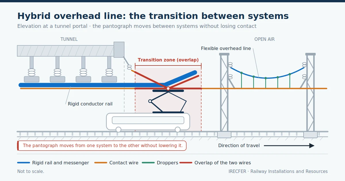
Few electrified lines are built with a single type of overhead contact line from end to end. As soon as an alignment enters a tunnel, passes under an underbridge with tight clearance or reaches an underground station, the system that works well on plain line no longer fits, and the technology has to change. When that change takes place within the same line, and the train moves from one system to the other without lowering the pantograph, the result is described as a hybrid overhead line.
The term, however, is not standardised. In its most widespread use within the electrification sector, a hybrid overhead line is the coexistence of two overhead line technologies along the same route: sections with an aluminium rigid conductor rail and sections of conventional flexible overhead line, joined by transition zones. In planning and rolling stock documents, by contrast, “hybrid” usually refers to electrifying only part of the route and leaving the rest without an overhead line, relying on battery trains.
This article deals mainly with the first case, which is the one that governs design, installation and maintenance: what happens where rigid conductor rail and flexible overhead line meet, why the transition zone concentrates most of the problems, and what it demands once the line is in service. The final section clarifies the other meaning.
What a Hybrid Overhead Line Means: The Different Senses of the Term
The first difficulty is semantic. “Hybrid overhead line” is not a category set out as such in the European standards framework for overhead contact lines, which does define catenary systems and pantograph interaction criteria precisely, but does not establish that name. It is a piece of professional usage, convenient and ambiguous in equal measure.
When a specification refers to a hybrid overhead line, it usually means a line in which two current collection systems coexist: the rigid overhead conductor rail, an extruded aluminium profile that houses the contact wire and holds it along its whole length, and the flexible overhead line, made up of a messenger wire from which the contact wire hangs on droppers, the vertical wires that transfer the weight of the contact wire to the messenger. Both feed the same pantograph, the collector mounted on the train roof, but they behave very differently.
At least two further senses circulate under the same name. One is that of lines with dual electrification systems, where two voltages or two types of current coexist and the train changes from one to the other at a system separation section: that is not a hybrid overhead line, but a line with a change of supply system. The other is discontinuous electrification, dealt with at the end. It is worth recording at outline design stage which meaning is being used, because the scope of works, the testing and the commissioning documentation differ in each case.
The Most Common Case: Rigid Conductor Rail and Flexible Overhead Line on the Same Line
The reason the two technologies end up coexisting is geometric and economic. The rigid conductor rail has a very small construction height, because it needs neither messenger wire nor droppers: the contact wire is seated in the groove of the aluminium profile, and the assembly is fixed to the tunnel crown or to the structure by supports spaced along the route. That makes it possible to electrify where the clearance between rail level and the roof is insufficient for a complete catenary.
The flexible overhead line is the natural solution on open plain line. It needs more height and a support infrastructure of its own, but it has far greater elasticity, allows high speeds with good current collection quality, and its cost per kilometre in open country is appreciably lower. Railway cantilevers, the bracket structures that carry the messenger wire and position the contact wire over the track, and overhead line foundations form a system already optimised for that situation.
The differences in behaviour explain everything else. The rigid conductor rail has a high mass per unit length and very low elasticity: it barely lifts under the pantograph, whereas a flexible overhead line lifts, oscillates and propagates waves along the span. The rigid conductor rail is not mechanically tensioned and expands with temperature, so it needs a fixed point and expansion joints at its ends; the flexible overhead line is tensioned by automatic tensioning devices that keep the tensile force constant through balance weights or springs, and absorbs expansion through longitudinal movement of the wires. They are opposite philosophies for solving the same problem, and where they meet the two have to be reconciled.
The Transition Zone: The Critical Point of the System
The transition is the stretch where the pantograph ceases to be in contact with one system and comes into contact with the other. It is the element that demands most attention in the whole hybrid installation, because it concentrates three discontinuities at once.
The first is the discontinuity in elasticity. The pantograph is running under a system that yields in a particular way and meets another that yields far less, or the other way round. If the change is abrupt, the contact force oscillates, and those oscillations cause loss of contact, arcing, accelerated wear of the contact wire and of the pantograph contact strip, and localised erosion of the transition components.
The second is the geometric discontinuity. Each system reaches the meeting point with its own contact wire height above rail level and its own stagger pattern, and the two need not coincide. The junction has to bring both variables together without steps or sharp changes of gradient, because the pantograph crosses them at line speed.
The third is the mechanical and thermal discontinuity. The end of the rigid conductor rail moves longitudinally as it expands, and that movement can neither be transmitted to the flexible overhead line nor be blocked against it. The transition has to allow relative movement between the two while maintaining electrical continuity and keeping the collection geometry within the permitted margins.
How the Transition Is Resolved: Overlap, Height Adjustment and Tensioning
The detailed solution depends on the conductor rail manufacturer, on the catenary system used on the line and on the infrastructure manager’s specifications, but the principles are common to all of them.
- Overlap of both systems. The same principle applies as at an overlap between tension lengths on a conventional line, with one difference: what runs in parallel along the common zone is not two equivalent contact wires but the flexible overhead line wire and the rigid conductor rail, which have very different stiffnesses. The overlap length is therefore set with more margin here than between two tension lengths of the same system.
- Entry termination of the conductor rail. The end of the rigid conductor rail does not stop at a square cut: it is finished with a terminal piece that rises and moves away from the collection plane, so that the pantograph never strikes an edge. That piece guides the entry and prevents the pantograph horn from catching.
- Progressive height adjustment. The heights of both systems are brought together within the overlap zone using gentle gradients. The nominal height and the maximum permissible gradient depend on the line, on the design speed and on the applicable specification, and are set in the construction design, not by analogy with another project.
- Elasticity transition. To smooth the change in stiffness, the geometry of the last spans of the flexible overhead line is adjusted: shorter spans, revised dropper spacing and, in some solutions, intermediate elastic components. The aim is for stiffness to vary gradually rather than in a step.
- Electrical continuity and mechanical freedom. The connection between the two systems is made with flexible conductors that accommodate the relative movement, and the contact wire of the flexible overhead line is taken to an independent anchor, so that automatic tensioning is not constrained by the conductor rail.
There are two families of solution according to how the wire is treated. In some, the contact wire of the flexible overhead line physically enters the groove of the rigid conductor rail and continues inside it, giving full continuity of the wire. In others, each system keeps its own wire and the handover takes place solely through the overlap, with the catenary wire anchored clear of the pantograph envelope once past the common zone. The choice governs the parts schedule, the installation procedure and how the line is subsequently adjusted.
Where It Occurs: Tunnel Portals, Underground Stations, Underbridges and Tight Clearances
Transitions are not placed where one would like, but where the infrastructure dictates. The typical locations are almost always the same.
- Tunnel portals. The most frequent case: the tunnel is electrified with rigid conductor rail to avoid enlarging the bore, and the plain line outside with a flexible overhead line. The transition is placed outside the tunnel, where it can be installed and adjusted comfortably and does not coincide with a turnout or a sharp curve.
- Underground stations and urban tunnelled sections. On metros and urban cross-city railways, rigid conductor rail is the standard solution under cover, and the flexible overhead line appears as soon as the line comes to the surface or reaches sidings and depots.
- Underbridges and structures with reduced clearance. A single underbridge with limited headroom can justify a short stretch of rigid conductor rail inserted between two stretches of flexible overhead line, with two transitions, rather than lowering the track or rebuilding the structure.
- Canopies and covered platforms. Where the canopy structure does not allow a messenger wire and its droppers to be hung, rigid conductor rail resolves the covered stretch while the rest of the station keeps conventional catenary.
- Depots and maintenance sheds. Shed interiors are electrified with rigid conductor rail or with switchable systems, and the connection with the outdoor access tracks requires a transition.
Advantages Over Installing a Single System Throughout
The alternative would be uniformity: either rigid conductor rail along the whole route, or a flexible overhead line forced through infrastructure where it does not fit. Neither usually works out well.
- Major civil works are avoided. Lowering the track level in a tunnel, enlarging its bore or rebuilding an underbridge so that a complete flexible overhead line will fit costs far more and takes far longer than installing a stretch of rigid conductor rail.
- Plain line performance is preserved. The flexible overhead line keeps its elasticity and its suitability for high speeds where there is room for it, without inheriting the limitations of rigid conductor rail along the whole route.
- Cost matched to each section. Rigid conductor rail has a high cost per metre and is justified where it brings something; extending it over tens of kilometres in the open is rarely reasonable.
- Robustness where access is difficult. Inside a tunnel, rigid conductor rail has hardly any moving parts and does not depend on tensioning devices, which reduces maintenance in an environment where every intervention consumes a possession.
- Flexibility for phases and extensions. A line extended with a tunnelled section can incorporate it without rebuilding the existing electrification, resolving the junction with a transition.
Risks and Typical Mistakes at Transitions
Almost all incidents associated with a hybrid line occur in the same place, and most of them originate in design or installation, not in operation.
- Locating the transition at an unfavourable point. Placing it over a turnout, in the middle of a curve, in a zone of changing cant or at the limit of a tension length complicates adjustment and multiplies the loads on the pantograph. The location is a design decision, not a site decision.
- A stiffness step with no gradual transition. Passing from the conductor rail to the free wire without adjusting the preceding spans produces contact force oscillations that show up as visible arcing and localised wear.
- Height and stagger errors within the overlap. A step in height, an excessive gradient or a badly resolved stagger reversal cause pantograph impacts and asymmetric wear of the contact strip.
- Failing to allow the conductor rail to expand. If longitudinal movement is restrained by the connection to the catenary, unforeseen forces appear in the supports, the conductor rail deforms and fixings work loose.
- Rigid electrical connections. Continuity bonds made with conductors that have insufficient slack fatigue under the daily thermal cycle and end in overheating and broken terminations.
- Tightening outside specification. Rigid conductor rail is held by bolted fixings whose tightening torque is a manufacturer’s figure; departing from it in the transition zone, where loads are highest, is a frequent cause of subsequent loosening.
- Incomplete documentation. A transition with no as-built parts schedule and no recorded adjustment values forces the maintenance team to reconstruct that information at every incident.
Installation and Maintenance: What a Line With Two Systems Demands
A hybrid line is not the sum of two independent installations, but one installation that requires two ways of working to be coordinated. The rigid conductor rail depends on structural anchors, on prior survey work and on lifting equipment suited to the tunnel clearance; the flexible overhead line depends on the civil works for supports, on wire running and on the tensioning devices. These are different sequences, with different productivity rates and with teams usually specialised in one technology or the other.
The transition is normally the last element to be built, because it requires both systems to be installed and pre-adjusted. That makes it a critical planning point: if one system falls behind, the transition is compressed against the end of the programme, and it is precisely where acceleration is least advisable. The sensible approach is to reserve specific possessions for fine adjustment of the overlap and for verification measurements, and to record the values obtained.
Pre-commissioning testing carries particular weight here. In addition to the usual geometric and electrical checks, the transition is proved with inspection runs and, depending on the scope of the project and on what the infrastructure manager requires, with pantograph-catenary interaction recordings that show whether contact force stays within the permitted range through the zone.
In service, overhead line maintenance on a hybrid line combines two plans with different criteria. The flexible section calls for monitoring of tensioning, droppers, steady arms — the arms that position the contact wire laterally — and tensioning devices. The rigid section calls for monitoring of fixings, expansion joints, contact wire wear within the groove and the condition of the supports. The transition zone is inspected more frequently than either, because it is where the signs appear first: arcing marks, irregular contact wire wear, loose bolts and height deviations.
Another Sense of the Term: Hybrid Electrification With Unwired Sections
The word “hybrid” is increasingly used in another sense, which should not be confused with the first. In infrastructure planning, hybrid or discontinuous electrification is an arrangement in which only certain sections of the route are electrified — those with the highest energy demand, the stations where trains stop, the gradients, or the sections where construction is straightforward — and the rest is covered by trains carrying batteries or another on-board energy source. The overhead line ceases to be continuous and becomes, in part, charging infrastructure.
Technically, that arrangement has nothing to do with the coexistence of rigid conductor rail and flexible overhead line. It affects decisions on rolling stock, on the sizing of traction substations and on where the electrified sections are placed, and its critical points are the catenary end terminations, where the pantograph is lowered or raised on the move, not the transitions between overhead line technologies. It also changes the load profile of the supply, because energy is concentrated in the electrified sections instead of being spread along the route.
The practical outcome is that the term, on its own, does not describe a system. When it appears in a specification or an invitation to tender, the first step is to ask what exactly is meant: sections of rigid conductor rail and sections of flexible overhead line joined by transitions, discontinuous electrification with battery rolling stock, or two supply systems. The scope of works, the testing and the risks differ in each case, and a misunderstanding over that one word is paid for during construction.
Conclusion
The coexistence of rigid conductor rail and flexible overhead line is not an anomaly, but the logical answer to a route whose conditions change. The relevant technical decision is not which of the two systems is better, but where one gives way to the other and how that change is executed. The performance of the whole installation is decided in the transition zones: well resolved, they go unnoticed for years; badly resolved, they generate recurring incidents at a fixed point on the route. And it is worth being precise about vocabulary from outline design onwards, because “hybrid overhead line” today denotes very different realities.
Do You Need to Resolve a Transition Between Rigid and Flexible Overhead Line?
IRECFER delivers railway electrification projects covering flexible overhead line, rigid conductor rail and the transition zones between them, together with traction substations, power lines, signalling and communications and the associated civil works, in Spain, Portugal, the Nordic countries and Latin America. We work both on new installations and on renewals and adaptations of lines in service. If you have a route with tunnels, underbridges or covered stations and need to define or deliver the electrification solution, contact us.

